• About
  • First time here?
  • Sitemap
  • Archives
  • Categories
  • Archive for February, 2015

    Pacifc Coast Extension: Progress Pics Pt.4


    2015 - 02.18

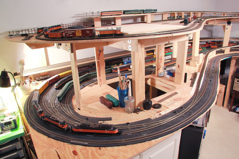
    Time for an update on the Pacific Coast Extension model railroad progress! When last we left off, I had just completed the upper deck benchwork and subroadbed (i.e. flat plywood) over the staging. As you can see in the photos, I’ve now completed the entire upper deck benchwork and subroadbed, which, like many things in this hobby, is a simple sentence to say but a huge amount of work to actually do.

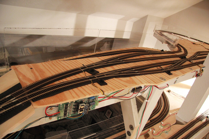
    I’ve also completed the inclined subroadbed which leads from the lower deck to the upper, although all the track is not yet in place there. A small section remains where three tracks of singled ended staging branch off. I added this area since I do enjoy running very long trains–long enough that some of them need to be broken up to fit in the double ended staging below. The wiring is installed for all new track mentioned in here as well. I did miss my self-imposed deadline of completing all mainline trackwork by the end of 2014 although since I only missed it by a couple weeks, I’m going to call that a win. Such deadlines are created to motivate oneself, and in that regard it was a success.

    the mountain loop (furthest "right" in these images)

    An autoreverser has been installed on the newly-completed mountain loop (shown above), although I’ve been struggling to get it to work correctly with the snap-coil switch motors which will allow a train to automatically run endless loops on the upper deck. Right now I’m thinking something just isn’t wired correctly and I need to spend the time to figure that out.

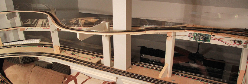
    The incline between decks never exceeded 4.5% as measured with my Micro Mark precision level, an invaluable tool. However it does appear quite steep visually and I know certain trains are definitely going to require helpers or multiple trips to make it up the grade between levels. That’s alright though, I’m okay with that. Real life worked the same way. Now if only MTH would hurry up and make some Boxcab motors.  Shown below is the large curve which will eventually be built into the Mine Creek trestle, and the incline between decks.  The plexiglass is there because that ledge is open to the living room, probably like 20 feet below!  This photo is looking just to the right of the one above.

    Mine Creek and deck connection

    To continue looking to the left of the photo above, here is another view, showing how the laypout wraps around the desk with a window behind it:

    IMG_7131 v2

    Speaking of the trains themselves, there are a few great new additions to the railroad. Foremost of these would be a Milwaukee Road creek series observation car, something available only in brass although fortunately it has been produced several times by different makers in the last several decades. I believe mine comes from the 1980s although I’m not sure. It has already been sent off for a custom paint job to match the Walthers cars, and I intended to further customize it by building an interior and adding lighting.

    Another beaut I’m delighted to have around is an MTH Little Joe in the orange and black freight scheme. Although my railroad is set in Washington state, there is a large amount of scenic overlap between Milwaukee’s Coast Division where the Bipolars ruled, and their Rocky Mountain division where the Joes ruled electric operations. That’s as far as I intend to ‘bend the rules’ at least at this point. Besides, any self-resepecting Milwaukee electrics modeler has got to have a Joe or three around; they’re debatably the most iconic of all Milwaukee Electrics, lasting from the 50s right up to the end.  You can see E73 in the picture below, which shows the staging area:

    IMG_7151 v2

    A few interesting things I’ve learned: Micro Engineering flextrack is great, especially if you use Peco track fixing pins along the edges of the ties, as opposed to large Atlas spikes on the center of the ties. This hides the spikes quite well and makes the track look more realistic. However it does hide the spikes so well you may accidentally do some damage trying to reposition the track later, by overlooking that hidden extra spike you put on the far side of the rail which is nearly impossible to see. ME flextrack also has a very annoying way of shortening the far end when bent even slightly–always check BOTH ends of the track before you cut any rail. And I do mean always.

    I’ve also ordered the supplies to commence with rock building on a large scale, which is a stage of construction I’ve LONG been itching to reach. I will have more details on that stage later this year.
    Electric Trumpet DIY pedalboard, phase 1


    2015 - 02.15

    In tandem with the ongoing speakerbuilding project keeping my garage dusty, I’ve also been working on a custom pedalboard for my electrified trumpet setup. This was born out of necessity since I’ve outgrown the footprint of my hardshell Rockcase board, which itself is getting worn out from years of schlepping. I make take some time to recondition it for any music that happens outside my living room. But since I’m a lucky dude who mostly gets to jam at home, I’ve started working on this:

    electric trumpet pedalboard

    Yep, it’s a jungle of wires and nothing is securely attached at this point, it’s true. Consider this a “version 1.0” photo. My goals here are 1. to accomodate more pedals at waist height for easy manipulation 2. to achieve a cleaner signal by isolating the audio cables away from any power supplies and power cables and 3. to hopefully make it look nice?

    As far as goal #1 (capacity), adding a second level was a slam dunk for me, which allows interactive pedals to be accessible on top and neccessary but non-interactive components to be stashed underneath. I’ve got a signal combiner and a DI box, both of which are key parts of my setup but neither of which need to be touched during an entire session, so these can be hidden away without taking up valuable real estate.

    To achieve goal #2 (a cleaner signal), I have relocated the power bricks, 9v power supply, and the power strip all to beneath the pedalboard, on their own little board. Moving all that away from the pedals was the most important step. To go further, I have bought a thin sheet of aluminum, which will cover the bottom of the board and then be electrically connected to the ground pin of the power strip so that it can serve as a ground plane to shield against any residual noise from the power supplies beneath it and maybe dampen any local RF. That has not been installed yet. Finally, wiring is obviously a jungle at the moment, but ultimately I want to route all power cables thrugh holes in the board so they come in contact with the audio cables as little as possible.   Interestingly, when I initially built the board, I had the elevated section on the right side, which I immediately realized was a terrible idea when I started to play in front of it for the first time–my LEFT hand is free to move knobs, not the right.  So I’m not in a tremendous rush to make things permanent, since I want to try some experimentation to find the best physical location for as many of these pedals as I can.  I’ll make a detailed breakdown of what I use at some point in the future.  Haven’t gotten to that yet.

    Making the board look good will be accomplished with wood stain and some stainless steel accents. And cleaning up that mess of cables! I’ll post another shot when she’s further along.  For now, here’s my perspective when playing on it:

    electric trumpet pedalboard - pilot's perspective

    Tycho Monitors, phase one


    2015 - 02.05

    As alluded to long ago in 2014, I bought some Scan-Speak drivers and associated hardware needed create a pair of hi-fi bookshelf speakers. I am just now finally getting around to building the enclosures for these guys. A few build photos are probably in order.

    Tycho Monitors in progress

    craftsmanship level = MEH.Everytime I build a new set of speakers (which doesn’t happen too often) I try out some new philosophies and these are no exception. Instead of solid MDF, this time I went with Red Oak. I’m not sure this wood is as great as it could be in terms of quality–I got it at Home Depot and if I were to do it again, I think I’d spend the extra to go get it from a legit lumberyard.

    This time I’ve also attempted to join each side with a 45 degree joint, which I don’t think I’d try again.  As you can see in the photo above, I used the 45 cuts as joiners on the inside as well.  Maybe I’m lacking the right tools to really pull this off. I did take probably a half hour or so playing around and dialing in my tracksaw to cut what I thought was a perfect 45 degree angle. I measured it with a level, protractor, and used two pieces pressed together with a carpenter’s square to verify they joined perfectly. Which they did, and yet, when I put the boxes together there is a thin line of open space around almost all sides, which I found equal parts surprising and disappointing. Somewhere in the process there was some looseness that prevented everything from lining up perfectly despite the fact that I took great care and worked slowly. Like I said, maybe a circular saw and track just can’t achieve perfection here.

    In any event, I’m forging onward and going to router out holes for the drivers next. Then there will be some variety of staining and/or lacquering before they’re ready to be used for real. Delayed gratification……